
Written by Chris Choi, Technical Sales Manager at MVS Lighting, with practical experience supporting overseas buyers on LED street lighting projects.
Fixture selection and pole spacing get most of the attention in road lighting design, but layout pattern — which side of the road the poles go on, and how they’re arranged relative to each other — is a separate decision that has just as much influence on whether a road actually hits its uniformity target. Get the spacing calculation right on the wrong layout pattern, and you’ll still end up with dark bands or an uneven, patchy result.
This is one part of the broader technical decision framework covered in our LED street light guide.
Why Layout Pattern Matters Independently of Spacing
Pole spacing answers “how far apart.” Layout pattern answers “on which side, and in what relationship to each other.” Both feed into the same uniformity outcome, but they’re determined by different factors — spacing comes largely from the photometric calculation, while layout pattern is driven primarily by road width, and secondarily by the road’s cross-section, surrounding land use, and what’s already running underground or overhead nearby.
Pole height is part of this too — it interacts with layout pattern to determine how far a fixture’s light needs to reach across the road. Our pole height guide covers how height and layout work together, including a practical sanity-check ratio used when reviewing a proposed staggered design.
Six layout patterns cover the large majority of road lighting projects: single-sided, staggered, opposite (double-sided symmetric), median twin-column, catenary center-span, and high-mast for a related but separate case.
Single-Sided Arrangement — Narrow Roads (Up to ~12m)
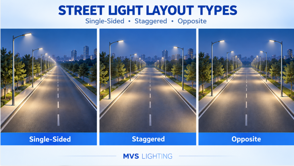
Single-sided arrangement places one evenly spaced row of poles along one side of the road. It’s the simplest layout to design and the least expensive to build, since it uses roughly half the poles of a double-sided approach for the same length of road.
It works well up to about 12m of carriageway width. Push it further and the far side of the road starts showing uniformity gaps that spacing adjustments alone can’t fully correct.
Which side the poles go on isn’t dictated by photometric requirements, but a few practical factors are worth checking before finalizing the layout: existing or planned overhead power lines should generally be avoided by placing the lighting row on the opposite side; on a ring or loop road, the outer side is typically preferred for a single row; and where a road runs alongside a river, canal, or other water feature, placing the poles on the water side is a common practice.
Staggered (Zig-Zag) Arrangement — Medium & Transitional-Width Roads
Staggered arrangement alternates poles between the two sides of the road rather than lining them up directly across from each other. It’s a useful middle option for roads that fall in an awkward width range — wide enough that single-sided lighting would need unusually tall poles to maintain uniformity, but not wide enough to justify the pole count and cost of a full double-sided layout. Roads around 14m wide are a common example of this transitional case.
The trade-off is aesthetic and technical: because the two sides aren’t symmetric, the visual result reads as less uniform to the eye than a symmetric layout, and design and construction need more precision to avoid uneven “zig-zag” brightness patterns if the offset spacing isn’t calculated correctly.
Opposite (Double-Sided Symmetric) Arrangement — Wide Roads (16m+)
Opposite arrangement places poles directly across from each other on both sides of the road, in matching symmetric pairs. It generally becomes the standard choice above about 16m of carriageway width, where a single row — staggered or otherwise — can no longer maintain uniformity across the full width on its own.
Beyond the photometric case for using it, symmetric double-sided arrangement is also simply what most people find visually appealing, and it’s a natural fit for projects where a distinctive fixture design is meant to be a visible part of the streetscape rather than a purely functional element.
The cost trade-off is straightforward: double the poles of a single-sided layout for the same length of road, which is the highest-cost option of the standard arrangement patterns.
Median Twin-Column Arrangement — Roads With a Central Divider
Where a road has a planted or paved median strip, poles can be placed in a single row down the center, each fitted with twin arms extending to both carriageways. This covers the main traffic lanes from one row of poles instead of two, which meaningfully reduces both pole count and cost. This layout requires fixtures built for bidirectional distribution — a standard single-sided fixture can’t simply be substituted in.
The trade-off is coverage: median twin-column arrangement lights the carriageways well but generally can’t adequately serve outer service roads or sidewalks from the same fixtures, since the throw distance to the road edge is longer than a roadside pole would need to cover. This makes it best suited to roads with a central median but no dedicated facility strip on the outer sides, or to lower-pedestrian-traffic suburban corridors where outer-edge lighting isn’t a priority.
Catenary Center-Span Arrangement — Narrow or Obstructed Streets
Catenary (span-wire) arrangement mounts a row of poles symmetrically on both sides of the street, connected by a horizontal cable strung across the road, with the light source suspended from that cable down the center of the road rather than mounted on an arm.
This solves a specific problem: narrow streets with no median, where dense roadside trees or tight building frontage make conventional arm-mounted fixtures impractical. It’s most often seen on older or historic streets where the road geometry predates modern lighting design standards.
Two practical drawbacks are worth flagging before specifying this approach: lighting quality at the outer sidewalks tends to be weaker than with roadside-mounted options, and a center-suspended fixture will sway in wind, which affects consistency of light distribution on the road surface over time compared to a fixed pole-mounted fixture.
A Related but Separate Case: High-Mast Lighting
High-mast lighting — typically poles in the range of 30m, carrying a cluster of light sources rather than a single fixture — solves a different problem than the six layout patterns above. Rather than a repeating row of standard poles, it provides wide-radius area coverage from fewer, taller installations. This becomes the practical choice at large interchanges and multi-lane ramp sections, where a conventional row of standard-height poles along a crash barrier would be both visually cluttered and difficult to fit around multi-lane ramp geometry that can’t accommodate guardrail-mounted fixtures. It’s a large enough topic on its own that we won’t cover it in depth here.
How to Choose the Right Layout for Your Road
Road width narrows the field to one or two realistic candidates — under 12m generally points to single-sided, 12–16m to staggered, and above 16m to opposite arrangement, with median and catenary options depending on whether a central divider or roadside obstruction is present rather than width alone.
Beyond width, it’s worth checking the road’s cross-section and what’s running underground before finalizing pole positions — planned utility corridors are typically routed around the facility strips reserved for lighting infrastructure, and pole foundations and buried low-voltage cable runs need that reserved space. Poles generally belong in the roadside or median facility strip and should never intrude into the road’s building clearance envelope.
Once a layout pattern is set, three decisions follow directly from it: the distribution type each fixture needs, since a staggered layout has different lateral coverage requirements than a symmetric one (see our distribution types guide); the actual pole spacing calculation for the chosen pattern and road classification (covered in full in our pole spacing guide); and, once spacing is confirmed, how many fixtures the project will actually need (see how many street lights a road project needs
The final layout should be verified with a lighting simulation based on your actual road dimensions rather than finalized on paper alone — see our road lighting design guide for what that verification involves.
FAQ
Does staggered arrangement need closer pole spacing than opposite arrangement? Not necessarily closer, but the spacing calculation differs — because each side only carries every other fixture, the effective spacing along a single side is roughly double what it would be in an opposite arrangement for the same overall pole density, and it needs to be verified against uniformity requirements rather than assumed.
Can single-sided arrangement work on a 15m wide road? Technically it can be installed, but it’s generally not recommended — at that width, single-sided lighting typically can’t maintain adequate uniformity on the far side of the road without pushing pole height and wattage well beyond what a staggered or opposite layout would require for the same result.
What’s the difference between staggered and median arrangement? Staggered arrangement alternates full poles between both sides of the road, with no central divider involved. Median arrangement places a single row of twin-arm poles in a central strip, serving both carriageways from the middle rather than alternating sides.
Not sure which layout pattern fits your road? Share your road width, cross-section, and whether a median or roadside obstruction is present, and our team can recommend a layout and provide a free DIALux lighting simulation to confirm it.
View the LED Street Light Series [Request a Free DIALux Lighting Simulation]